Assembly – head unit
Parts to buy, printing, screw joints and the order of assembly. The electrical connections are in the Wiring guide.
Small parts to buy – HESTORE (Hungarian electronics shop)
Prices are not listed – check the product pages. The links point to HESTORE product pages; any equivalent part will do.
| Item | Qty | HESTORE | Where it goes |
|---|---|---|---|
| M2 × 6 screw, stainless (M 2 x 6 DF) | 6 | prod_10030973 | lid → housing: 2 at the back (corner blocks); eyepiece: 4 (2 top, 2 bottom) – all into M2 nuts |
| M2 × 10 socket head screw, DIN 912 (B2X10-BN610) | 1 | prod_10051167 | spring stop → shaft (the head sits in the 2 mm deep counterbore) |
| M2 hex nut, stainless (M 2 HTL) | 7 | prod_10030969 | lid nut traps (2) + eyepiece (4) + spring stop (1) |
| Compression spring, inner Ø7.1, outer Ø8.9, free length 35 mm | 1 | from the parts drawer | on the hook shaft |
| Self-adhesive copper tape, 3M, 25 mm × 16.5 m | 1 | prod_10038370 | 2 touch pads, cut to a 10 × 16 mm capsule shape (the recess is the template) |
| Enamelled copper wire Ø0.15 mm, 100 m (CWW15) | 1 | prod_10037152 | touch pad wires |
| Kapton tape, 3M 1218, 12 mm | 1 | prod_10030270 | insulation (back of the display module, solder joints) |
| SMD0805 560 Ω resistor | 2 | prod_10001186 | series resistor in the touch lines (Espressif: 470 Ω–2 kΩ) |
| Thin rubber/felt (self-adhesive) | – | hardware store | on the hook and on the inner side of the housing (so the temple does not slip) |
| MAX98357A I2S amplifier module (MAX98357-M) | 1 | prod_10045704 | audio |
| 100 kΩ 1% metal film resistor, 0.6 W | 1 | prod_10020564 | amplifier GAIN → Vin (3 dB) |
| 150 Ω 1% metal film resistor, 0.6 W | 2 | prod_10020496 | series resistors for the earphone (hearing protection) |
| Thin double-sided tape (approx. 0.8 mm) | – | hardware store | amplifier onto the inner wall |
| Double-sided foam tape, 1 mm thick (strong, e.g. 3M VHB type) | – | hardware store | under the XIAO, between the two end supports |
| Earphone (wired, right side) | 1 | any old one | the right speaker with a few cm of cable |
Optional: M2 heat-set threaded inserts (INSERT-SET-M2-500P, prod_10052278) – more durable than a thread cut into PLA, but the model would need larger holes and bosses (it is not designed that way now).
Printing (PLA)
| Part | Orientation | Notes |
|---|---|---|
| Housing | standing on its base, open top facing up (as in the STL) | Built-in support under the display window bridge (break it out after printing); the top of the USB opening is a 45° chamfer + a short bridge. Slicer supports off. 0.2 mm layers, 3–4 walls. |
| Lid | on its back, flipped 180° (as in the STL) | No support needed. |
| Eyepiece | on its 45° back wall (as in the STL) | Built-in support under the side of the sleeve facing the bed – break it out after printing and sand the spot lightly. Do not enable slicer supports. |
| Hook | on its side, the plane of the hook on the bed (as in the STL) | No support needed; the layers run in the plane of the hook, so the bends are strong. 100% infill or 5–6 walls recommended. |
| Spring stop | on its side, round face on the bed (as in the STL) | No support needed. |
- At the touch pads the wall is 1.8 mm, printed solid (the walls are made of perimeters, so there is no air gap). Stick the copper foil into the recess, thread the wire through a Ø1 mm hole drilled in the middle of the pad, then sand and paint – the paint is the cover.
- It is worth painting the inner surfaces matt black (against stray light).
Screw joints: no threads in the PLA
Every screw goes into a metal nut or a metal screw; no thread is cut into a printed part: - lid: M2 nuts in the side nut traps of the two rear corner blocks of the housing; - eyepiece: 4 M2 screws through the sleeve, the nuts in the bosses under the lid (top) and on the floor (bottom); - spring stop: M2 × 10 screw through the shaft (drill the hole through the stop), the nut in the lower pocket of the stop.
Mounting on the temple: spring-loaded hook
- The inner side of the housing (Y = 0) rests against the outer side of the temple; the temple runs at half the height of the housing.
- The hook goes into the 5–7 mm gap between the temple and the head (the hook is 6 mm thick).
- To put it on: push the shaft end sticking out on the outer side of the housing towards the head, hook it onto the temple, release.
- Thin rubber or felt can be glued to the inside of the hook and to the side of the housing so it does not slip.
Audio: amplifier and earphone
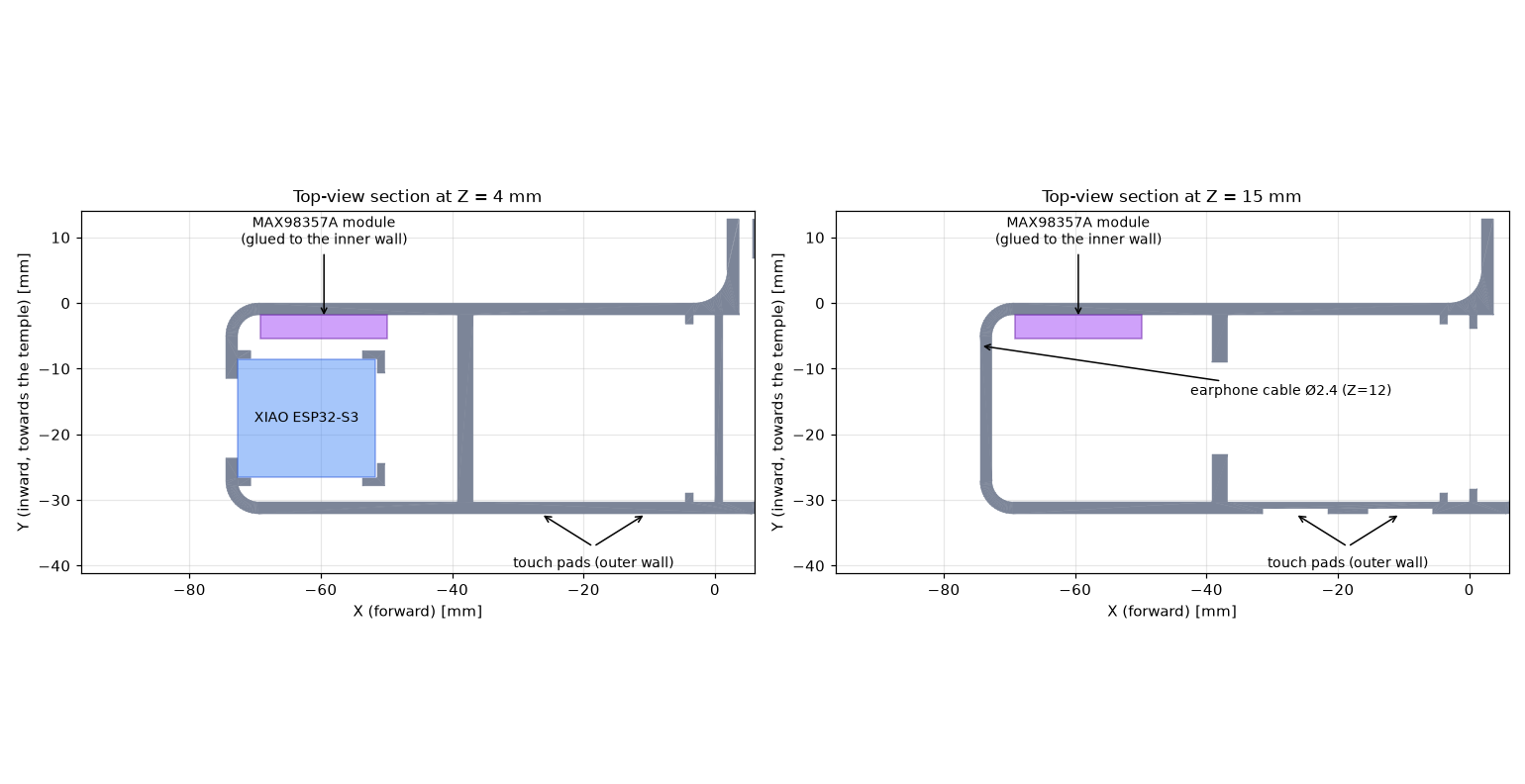
The MAX98357A I2S amplifier module (approx. 19.3 × 17.8 mm) goes vertically onto the inner wall (towards the temple), with the back of the board against the wall, using double-sided tape. It starts 3 mm from the rear wall (the earphone cable comes in behind it) and stands on the floor next to the XIAO. The touch pads are on the opposite, outer wall, so the I2S wires do not disturb them. The earphone cable leaves through a Ø2.4 mm hole in the rear wall (Y = −6.5, Z = 12 mm). Inside, a knot or a drop of hot glue relieves the strain.
To make room, the XIAO is shifted 1.5 mm towards the outer wall (with its cradle and the USB-C opening), which leaves 2.3 mm between the XIAO and the amplifier components; the rear corner blocks are 6 mm tall.
Top-view section of the rear compartment: kepek/amplifier_position.png
Connections, resistors, hearing protection: see the Wiring guide.
Assembly (suggested order)
- XIAO ESP32-S3 into the rear compartment, into the cradle: USB-C at the rear opening, the board rests on its two ends (2 mm cross supports), the four corner guides hold it sideways, and the two front corner guides take the force of plugging in the USB-C (the rear wall takes it when unplugging). Put 1 mm double-sided foam tape between the two supports. Under and beside the two long sides (the pin rows) there is room for the wires. Solder the wires and plug in the antenna before seating the board.
- Display module (28 × 34 × 3 mm, with the display still on its board) from above into the slot, behind the frame, ribbon side down, the hole strip up. The wires go back from the holes to the XIAO.
- Connections (see the Wiring guide); touch pad wires through a Ø1 mm hole drilled in the middle of each pad. - Amplifier: after soldering the wires, glue the module onto the inner wall (against the rib at the front and the floor at the bottom). Thread the earphone cable from outside through the Ø2.4 hole in the rear wall, tie a knot inside, then solder it through the two 150 Ω resistors to OUT+ / OUT−. Neither earphone wire may go to GND. - There are only two pads (A and B); their wires go directly to the XIAO D0 and D1 pins. - Thin enamelled wire (0.1–0.2 mm) or 34–36 AWG, each fixed with a drop of glue; then paint the inside matt black. - Do not run the touch wires parallel to the SPI wires; cross them at a right angle (Espressif recommendation).
- Fold mirror (M2, 33 × 33 × 2 mm) from above onto the 45° wall, glued (thin double-sided tape over the whole surface), mirror side towards the cavity. There is no holder post.
- Lens (Ø28, f = 92 mm) from inside, through the open end of the eyepiece (slightly tilted) into the seat of the exit opening, flat side towards the eye mirror, convex side towards the eye; fix it at the edge of the seat with 1–2 dots of hot glue or neutral silicone (no superglue, see below).
- Hook: insert the shaft into the round hole on the head side, thread it inside the housing through the spring, then through the spring stop (nut in its pocket, counterbore on top), and push it out through the hole on the outer side. Compress the spring as much as you like, drill the shaft through the Ø2.3 hole of the stop, and fix it with the M2 × 10 screw. Slide the two M2 nuts into the side traps of the rear corner blocks (tweezers, a drop of glue; no superglue near the optics). Put the two upper nuts of the eyepiece into the bosses under the lid (from the side, from inside the housing) and the two lower ones into the bosses on the floor (from above). Place the lid straight down from above (its skirt wraps around the box) and screw it into the nuts at the back with the 2 M2 × 6 screws.
- Eye mirror (M3, 32 × 25 × 2 mm, the lower corner on the lens side cut off in an arc according to the template) slid in through the open end of the eyepiece, mirror side towards the cavity, its back glued to the solid 45° back wall; it stands on the 0.5 mm floor ledge.
Cutting the mirrors (2 mm thick acrylic front-surface mirror): M2 = 33 × 33 mm rectangle, M3 = 32 × 25 mm with the bottom-left corner cut off in an arc (seen from the mirror side). 1:1 template: kepek/mirror_template.pdf – print at 100% and check it with the 50 mm ruler. The mirror is plastic: - Cutting: leave the protective film on, score several times along a ruler with a sharp scalpel or an acrylic knife, then snap it over the edge of a table. A fine-toothed saw also works. Smooth the cut edge with fine sandpaper. - The mirror coating scratches very easily: hold it only by the edges and remove the film right before fitting. Cleaning: blow it off, at most a dry or slightly damp microfibre cloth. No acetone or solvents. - It must stay flat: a thin plastic mirror bends easily, and then the picture is distorted. Both mirrors lie over their whole surface on a solid 45° wall. Glue the back with even, thin double-sided tape; do not clamp it at the edges. - No superglue (cyanoacrylate) near the mirrors and the lens: its fumes leave a white, hazy deposit on plastic optics. Use thin double-sided tape, hot glue or neutral silicone instead. 8. Slide the sleeve of the eyepiece onto the end of the arm (up to the stop) and screw it into the nuts with the 4 M2 × 6 screws (2 top, 2 bottom). There is no angle adjustment.